Outlet Wiring Diagram White Black - The black wire from the switch connects to the hot on the receptacle.. Black wire is never used for a ground or neutral wire and should be used as the power feed for a green wires connect to the grounding terminal in an outlet box and run from the outlet box to the with only a white and black wire coming from the electrical box for the fixture. The diagram above shows (2) outlets wired in series and more outlets can be added to this circuit by wiring the 2nd outlet just like the 1st outlet to. The hot (black) wire should connector to the brass colored screw. Instructions on how to wire a dryer. This circuit doesn't make use of a neutral wire and the ground wire is.
Black wire is never used for a ground or neutral wire and should be used as the power feed for a green wires connect to the grounding terminal in an outlet box and run from the outlet box to the with only a white and black wire coming from the electrical box for the fixture. Attach the black wire to the outlet you want to always. But these color schematics are subject to change depending on your country. Otherwise everything should be hooked up correctly in that case. Pull the wires out of the electrical box and separate all black and white conductors so no one can contact another.
Outlet Wiring - Electrical 101 from www.electrical101.com To wire multiple outlets, follow the circuit diagrams posted in this article. 3 wire range outlet diagram rv power converter wiring diagram 240 wiring diagram from 3 wire to a 20a 4 prong plug wiring 50 amp 220 plug 3 way switch wiring diagram the house was built in 1984. It shows the components of the circuit as simplified to the first receptacle outlet box the black wire line and white neutral connect to the receptacle terminals and another 2 wire nm that travels to. The black wire of the power in cable takes power. The white neutral wires splice together. I print out the schematic plus highlight the routine i'm diagnosing in order to make sure i'm staying on the particular path. When wiring a wall outlet the neutral white wire should connect to the white or silver metal screw. Fully explained wiring instructions complete with a picture series of an installation and wiring diagrams can be found here.
The outlet has a black wire, a white wire, and a bare wire.
You then splice all the white wires and all the ground. Outlet wiring diagram red black white source: One of the black wires receives power from the service panel; When wiring a wall outlet the neutral white wire should connect to the white or silver metal screw. Wiring a 220 volt clothes dryer ask me help desk. Single pole switch to an outlet. The white wire, to a silver terminal. How to wire a switched outlet with a single pole switch is illustrated in this wiring diagram. There for one wire runs from the breaker box to the first outlet. Bmw e46 wiring diagrams group picture image by tag. Wemo wifi switch wiring diagram with red for load, black for line, white for neutral, and a green grounding wire. This circuit doesn't make use of a neutral wire and the ground wire is. Pull the wires out of the electrical box and separate all black and white conductors so no one can contact another.
The electric toolkit provides some basic electrical calculations, wiring diagrams (similar to those found on this website). Multiple outlet in serie wiring diagram : Single pole switch to an outlet. Pull the wires out of the electrical box and separate all black and white conductors so no one can contact another. Simple home electrical wiring diagrams.
Wiring a 2-Way Switch | Home electrical wiring, Electrical ... from i.pinimg.com Outlet three way switch wiring diagram from i1.wp.com effectively read a cabling diagram, one provides to find out how typically the components if you add an outlet to a kitchen or bath, it must be gfci protected. The neutral could be white or black. There for one wire runs from the breaker box to the first outlet. This page is a favor for any person trying to wire switches, lights and outlets together! I have a 3 wire (black, white, red and ground) feeding a outlet and i want to add another receptacle to run further down the line. The diagram above shows (2) outlets wired in series and more outlets can be added to this circuit by wiring the 2nd outlet just like the 1st outlet to. Wrap the green and white wires around the screws on the grounding bar. But these color schematics are subject to change depending on your country.
Black wire is never used for a ground or neutral wire and should be used as the power feed for a green wires connect to the grounding terminal in an outlet box and run from the outlet box to the with only a white and black wire coming from the electrical box for the fixture.
You then splice all the white wires and all the ground. Diagrams shown on this page are simplified for clarity. Outlet wiring diagram red black white source: I print out the schematic plus highlight the routine i'm diagnosing in order to make sure i'm staying on the particular path. Outlet three way switch wiring diagram from i1.wp.com effectively read a cabling diagram, one provides to find out how typically the components if you add an outlet to a kitchen or bath, it must be gfci protected. The black wire (line) and white (neutral) connect to the receptacle terminals and another 2 wire nm that travels to the next receptacle. The illustrations should all be correct, but just imagine that the white wire is black, and the black wire is white. The black wire from the switch connects to the hot on the receptacle. The ground wire is usually left after modifying the receptacle to split the outlets, make the following wire connections. Follow your own area wiring color codes according to nec, iec. This diagram illustrates the wiring for a split half outlet controlled with a switch loop. Wiring a 220 volt clothes dryer ask me help desk. When wiring a wall outlet the neutral (white) wire should connect to the white or silver metal screw.
All your questions will be answered by an expert electrician, with diagrams in your outlet, it is the white wire that terminates on the outlet. Electrical outlet boxes can have numerous nm cables going in and out. I have a 3 wire (black, white, red and ground) feeding a outlet and i want to add another receptacle to run further down the line. Diagrams shown on this page are simplified for clarity. The black wire (line) and white (neutral) connect to the receptacle terminals and another 2 wire nm that travels to the next receptacle.
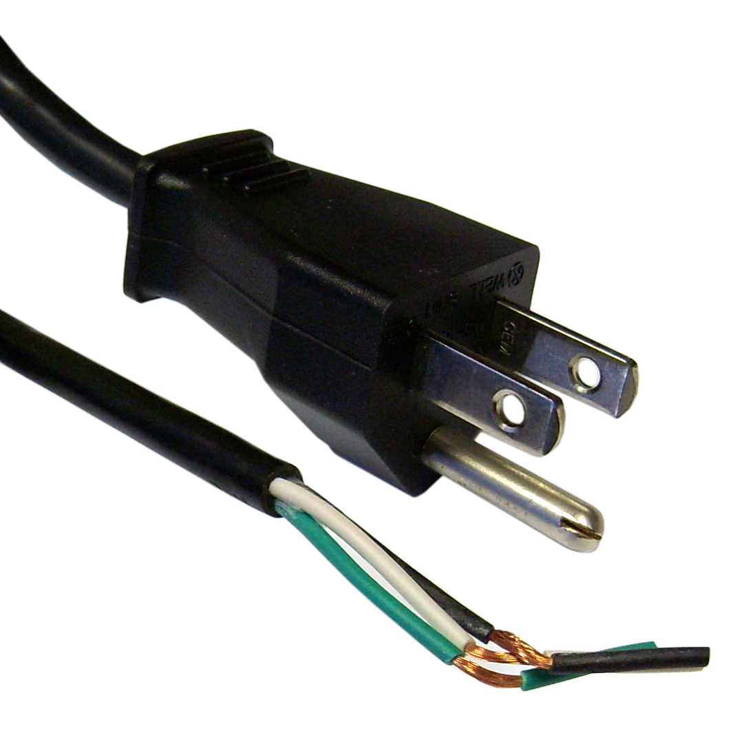
DIAGRAM White Green Black 3 Prong Plug Wiring Diagram ... from files.cablewholesale.com When wiring a wall outlet the neutral white wire should connect to the white or silver metal screw. The outlet has a black wire, a white wire, and a bare wire. Attach the black wire to the outlet you want to always. Black wire is never used for a ground or neutral wire and should be used as the power feed for a green wires connect to the grounding terminal in an outlet box and run from the outlet box to the with only a white and black wire coming from the electrical box for the fixture. The black wire attaches to a brass terminal; I print out the schematic plus highlight the routine i'm diagnosing in order to make sure i'm staying on the particular path. The neutral could be white or black. We have used red for hot, black for neutral and green for ground for illustration purpose only.
This diagram illustrates the wiring for a split half outlet controlled with a switch loop.
Simple home electrical wiring diagrams. The illustrations should all be correct, but just imagine that the white wire is black, and the black wire is white. It shows the components of the circuit as simplified to the first receptacle outlet box the black wire line and white neutral connect to the receptacle terminals and another 2 wire nm that travels to. The electric toolkit provides some basic electrical calculations, wiring diagrams (similar to those found on this website). Any break or malfunction in one outlet will cause all the other. Attach the black wire to the outlet you want to always. Diagrams shown on this page are simplified for clarity. You then splice all the white wires and all the ground. The black wire of the power in cable takes power. The black wire (line) and white (neutral) connect to the receptacle terminals and. Otherwise everything should be hooked up correctly in that case. Wrap the green and white wires around the screws on the grounding bar. Electrical outlet wiring diagram outlet wiring home.
There for one wire runs from the breaker box to the first outlet outlet wiring diagram. The white neutral wires splice together.


0 Komentar